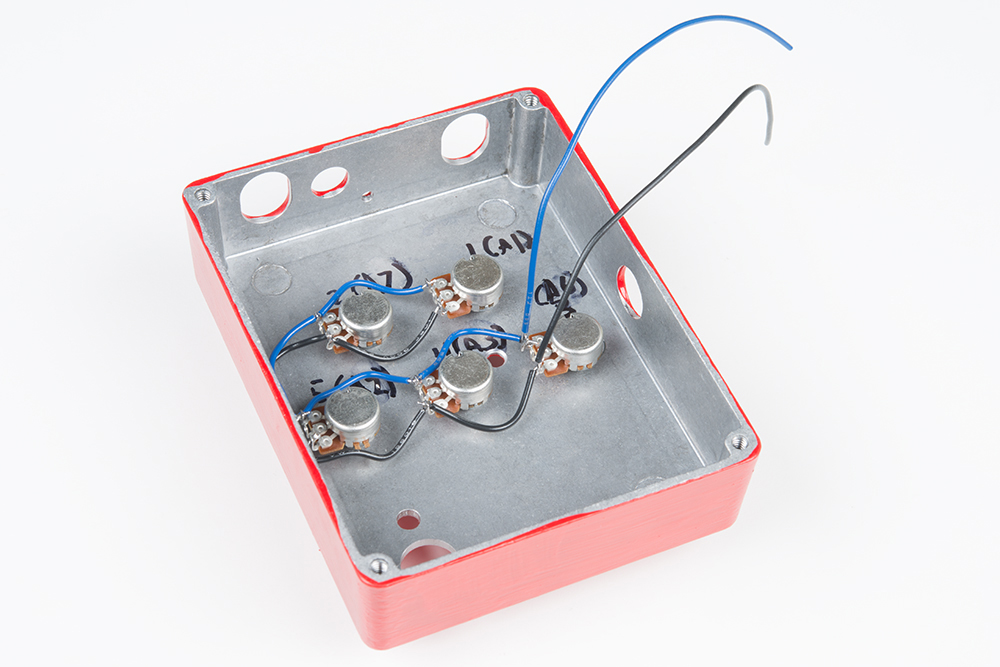
I know I am sounding silly, but when the wires are attached by hand, that seems like hand wiring to me (told ya I was silly). Hand wired and PTP are the same now? or are they different things this time? Turret, eyelets? This part gets hazy, could someone who just got their first magic pre-beaten-up guitar and starting reading the internet guitar forums last week please set the rule? If a pedal is built by hand, and all wiring is done by hand and is on a PCB with pads only but no traces, it is hand wired?

If a pedal is built by hand, and all wiring s done by hand, but it is on a PCB with traces, it is not hand wired?

Pcb pedal update#
UPDATE 04.2021: Updated download links by request, all files should be available now.I think we should have "definition threads" at least once a week. Wiring Diagram Note: potentiometer shafts on the wiring diagram are positioned away from the viewer.ĭownload Below I have included all needed files to build this project. It is easy to connect all off-board components and position them how you want to in a case. Wiring Diagram I have made a wiring diagram to make building this pedal as simple as possible for you.
Pcb pedal Pc#
Other: Opamp MC1458P – 2 pcs Diode 1N4148 – 2 pcs Diode 1N4007 – 1 pc LED 9V DC Jack – 1 pc 9V Battery Clip – 1 pc Audio Jack 6,35mm stereo – 1 pc Audio Jack 6,35mm mono – 1 pc 3PDT Button – 1 pc Potentiometers: 500K LIN – 1 pc 20K LIN – 1 pc 100K LOG – 1 pc PCBĬomponents list It is a basic analog scheme, so not so many components can be found in this one. I will have the picture right down below, but if you want, you can download Sprint Layout files in the end of the post. The PCB turned out to be almost the same as the Matsumin version, but I was sure that it was right with all the measurements. I can say, that I had genuine fun while trying to route the PCB. PCB As for the PCB, I could have used the one on the Matsumin website, but I wanted it to be done by me just to be sure and have better quality for a print. Schematic For principle schematic, I found a good one on a Japanese website:
Pcb pedal trial#
After some trial and error, I finally got the schematic working. Considering I was only starting out in the DIY projects, this pedal build was rather hard. We will not go into any details right now, maybe in another post. These opamps are two JFET transistors in one package, but with different characteristics, which gives them difference in sound.

Compared to Tube Screamer, which uses JFET transistors, Maxon OD808 uses operational amplifiers, or opamps for short. Inside there is a modified schematic of the very first Tube Screamer. This pedal has a lot of history and is as popular as a Tube Screamer TS9 by Ibanez.

Introduction Original Maxon Pedal Today I want to present you my second project – DIY Maxon 808 Overdrive pedal.


 0 kommentar(er)
